Vision guidance is used in situations where the combination of tolerance stack-ups, beam diameter, and feature size would cause inconsistent welds.
The Challenge With Precision Laser Welding
When you manufacture medical devices, automotive sensors, and other intricate products, failure is not an option. With tight tolerances and complicated assembly processes, consistently laser welding complex components can be a difficult task to accomplish and maintain over a long period of time in a production environment.
The focused spot diameter for laser welding applications is typically 100-1,000 microns. The position of the joint under the laser must be precise enough to ensure that the focused spot does not miss.
The allowable misalignment is a function of the focused beam diameter as well as the joint design and is typically in the range of ±75 microns.
For many applications, hard tooling is sufficient to locate the part for welding. However, in applications where part tolerances exceed ±75 microns, active positioning of the weld joint and/or laser spot are required for an accurate, consistent weld.
Bringing Vision Guidance to Laser Welding
Invotec Engineering has integrated vision-guided laser welding systems into a wide range of custom equipment—including laser spot welders, seam welders, and laser machining centers—to solve complex welding problems for the medical device, automotive, and defense industries.
Here’s how it works:
A vision inspection system is used to determine where the focal point of the laser energy will land relative to the features to be welded.
Once the offsets are determined, a servo positioning system moves either the terminal optics or the parts to be welded, ensuring the energy is delivered to the correct weld location.
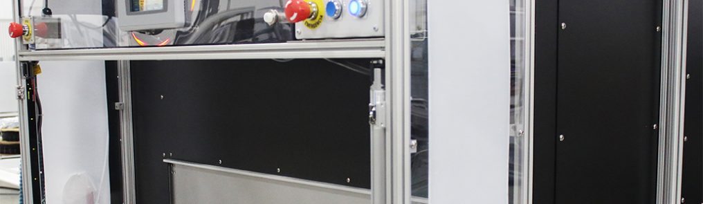
These photos demonstrate the accuracy of a vision-guided laser weld as opposed to a traditional weld. In the first photo, the magenta line is the position of the weld seam. The yellow line is where a traditional laser welding system will place the weld seam. This would produce a rejected part.
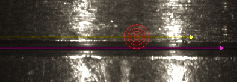
In the second photo, the system automatically aligns the laser path with the weld seam. The red welding target is now properly placed on the seam. The result is an approved part each time.
By incorporating vision-guided laser welding systems, our customers automate previously manual weld operations—improving weld quality and consistency, reducing scrap, and increasing throughput.
Share this Post